Keypad, LCD interfacing with LPC2148
Keypad interfacing can be done with the Microcontroller by means polling and interrupts. Since interrupts will not fit when interfacing large number of keys so polling becomes the ultimate choice. Polling is nothing but making the rows of the keypad as input and column as output or vice versa.
Keypad interfacing can be done with the Microcontroller by means polling and interrupts. Since interrupts will not fit when interfacing large number of keys so polling becomes the ultimate choice. Polling is nothing but making the rows of the keypad as input and column as output or vice versa.
Keypad Structure:
 |
| Structure of Keypad |
Interfacing diagram:
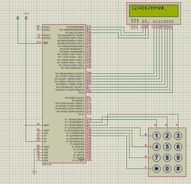 |
| Interfacing Diagram of Keypad , LCD with LPC2148 |
Code
1) Keypad, LCD interfacing with LPC2148 (using if and while loop)
1) Keypad, LCD interfacing with LPC2148 (using switch case)
1) Keypad, LCD interfacing with LPC2148 (using if and while loop)
/**************************************************************************************************
Expt. .: Keypad,LCD interfacing with to LPC2148
Platform:  LPC2148 Development Board.
College: PICT
Hardware Setup:-
Keypad columns - P1.16, P1.17, P1.18
Keypad rows - P1.19, P1.20, P1.21, P1.22
LCD Data lines- P0.16 - P0.23
LCD Control lines- P0.0, P0.1, P0.2
********************************************************************************/
#include <lpc21xx.h>
#define RS (1<<0)
#define RW (1<<1)
#define E (1<<2)


void LCD_command(unsigned char command);
void  delay_ms(unsigned char time);
void LCD_data(unsigned char data);
void LCD_init() ;


int main(void)
{
 //PINSEL1 = 0x00000000;  //Configure PORT0 as GPIO
 //PINSEL2 = 0X00000000;  //Configure PORT1 as GPIO
 IODIR1= 0x00780000; //Configure P1.18, P1.17, P1.16 as output(for rows and column)
 IODIR0= 0x00FF0007;  //Configure P0.23 - P0.16 as output for lcd data & P0.0,P0.1,P0.2 for lcd control lines.
 LCD_init();    //Initialize LCD 16x2
 LCD_command(0x01);
 while(1)
   {
      IOCLR1|=(1<<19);               //Making row1 LOW
      IOSET1|=(1<<20)|(1<<21)|(1<<22); //Making rest of the rows '1'
      if(!(IOPIN1&(1<<16)))             //Scan for key press
       {
        while(!(IOPIN1&(1<<16)));
        LCD_data('1');
       }
      if(!(IOPIN1&(1<<17)))
       {
         while(!(IOPIN1&(1<<17)));
          LCD_data('2');
       }
      if(!(IOPIN1&(1<<18)))
       {
         while(!(IOPIN1&(1<<18)));
          LCD_data('3');
       }
      IOCLR1|=(1<<20);
      IOSET1|=(1<<21)|(1<<22)|(1<<19);
      if(!(IOPIN1&(1<<16)))
{
        while(!(IOPIN1&(1<<16)));
         LCD_data('4');
      }
      if(!(IOPIN1&(1<<17)))
{
        while(!(IOPIN1&(1<<17)));
         LCD_data('5');
     }
      if(!(IOPIN1&(1<<18)))
{
        while(!(IOPIN1&(1<<18)));
         LCD_data('6');
     }
      IOCLR1|=(1<<21);
      IOSET1|=(1<<22)|(1<<20)|(1<<19);
      if(!(IOPIN1&(1<<16)))
{
        while(!(IOPIN1&(1<<16)));
         LCD_data('7');
     }
      if(!(IOPIN1&(1<<17)))
{
       while(!(IOPIN1&(1<<17)));
        LCD_data('8');
    }
      if(!(IOPIN1&(1<<18)))
{
        while(!(IOPIN1&(1<<18)));
         LCD_data('9');
}
      IOCLR1|=(1<<22);
      IOSET1|=(1<<19)|(1<<20)|(1<<21);
      if(!(IOPIN1&(1<<16)))
{
        while(!(IOPIN1&(1<<16)));
         LCD_data('*');
}
      if(!(IOPIN1&(1<<17)))
{
        while(!(IOPIN1&(1<<17)));
         LCD_data('0');
}
      if(!(IOPIN1&(1<<18)))
{
        while(!(IOPIN1&(1<<18)));
         LCD_data('#');
}
   }
}


//Function to generate software delay
//Calibrated to 1ms
void  delay_ms(unsigned char time)
{
 unsigned int  i, j;
 for (j=0; j<time; j++)
 {
  for(i=0; i<8002; i++)
  {
  }
}
}

void LCD_command(unsigned char command)
{
 IOCLR0 = 0xFF<<16; // Clear LCD Data lines
 IOCLR0=RS;     // RS=0 for command
 IOCLR0=RW;     // RW=0 for write
 IOSET0=command<<16; // put command on data line
 IOSET0=E;   // en=1
 delay_ms(10) ;   // delay
 IOCLR0=E;    // en=0
}

void LCD_data(unsigned char data)
{
 IOCLR0 = 0xFF<<16; // Clear LCD Data lines
 IOSET0=RS;     // RS=1 for data
 IOCLR0=RW;     // RW=0 for write
 IOSET0= data<<16;  // put command on data line
 IOSET0=E;   //en=1
 delay_ms(10) ;    //delay
 IOCLR0=E;   //en=0
 }

void LCD_init()
{
 LCD_command(0x38); //8bit mode and 5x8 dotes (function set)
 delay_ms(10) ;   // delay
 LCD_command(0x0c); //display on, cursor off, cursor char blinking off(display on/off)
 delay_ms(10) ;   // delay
    LCD_command(0x0e);  //cursor increment and display shift(entry mode set)
    delay_ms(10) ;   // delay
 LCD_command(0x01);  //clear lcd (clear command)
 delay_ms(10) ;   // delay
 LCD_command(0x80);
  delay_ms(10) ;//set cursor to 0th location 1st lne

}
/**************************************************************************************************
Expt. .: Keypad,LCD interfacing with to LPC2148
Platform:  LPC2148 Development Board.
College: PICT
Hardware Setup:-
Keypad columns - P1.16, P1.17, P1.18
Keypad rows - P1.19, P1.20, P1.21, P1.22
LCD Data lines- P0.16 - P0.23
LCD Control lines- P0.0, P0.1, P0.2
********************************************************************************/
#include <lpc21xx.h> #define RS (1<<0) #define RW (1<<1) #define E (1<<2) void LCD_command(unsigned char command); void delay_ms(unsigned char time); void LCD_data(unsigned char data); void LCD_init() ; int main(void) { //PINSEL1 = 0x00000000; //Configure PORT0 as GPIO //PINSEL2 = 0X00000000; //Configure PORT1 as GPIO IODIR1= 0x00780000; //Configure P1.18, P1.17, P1.16 as output(for rows and column) IODIR0= 0x00FF0007; //Configure P0.23 - P0.16 as output for lcd data & P0.0,P0.1,P0.2 for lcd control lines. LCD_init(); //Initialize LCD 16x2 LCD_command(0x01); while(1) { IOCLR1|=(1<<19); //Making row1 LOW IOSET1|=(1<<20)|(1<<21)|(1<<22); //Making rest of the rows '1' if(!(IOPIN1&(1<<16))) //Scan for key press { while(!(IOPIN1&(1<<16))); LCD_data('1'); } if(!(IOPIN1&(1<<17))) { while(!(IOPIN1&(1<<17))); LCD_data('2'); } if(!(IOPIN1&(1<<18))) { while(!(IOPIN1&(1<<18))); LCD_data('3'); } IOCLR1|=(1<<20); IOSET1|=(1<<21)|(1<<22)|(1<<19); if(!(IOPIN1&(1<<16))) { while(!(IOPIN1&(1<<16))); LCD_data('4'); } if(!(IOPIN1&(1<<17))) { while(!(IOPIN1&(1<<17))); LCD_data('5'); } if(!(IOPIN1&(1<<18))) { while(!(IOPIN1&(1<<18))); LCD_data('6'); } IOCLR1|=(1<<21); IOSET1|=(1<<22)|(1<<20)|(1<<19); if(!(IOPIN1&(1<<16))) { while(!(IOPIN1&(1<<16))); LCD_data('7'); } if(!(IOPIN1&(1<<17))) { while(!(IOPIN1&(1<<17))); LCD_data('8'); } if(!(IOPIN1&(1<<18))) { while(!(IOPIN1&(1<<18))); LCD_data('9'); } IOCLR1|=(1<<22); IOSET1|=(1<<19)|(1<<20)|(1<<21); if(!(IOPIN1&(1<<16))) { while(!(IOPIN1&(1<<16))); LCD_data('*'); } if(!(IOPIN1&(1<<17))) { while(!(IOPIN1&(1<<17))); LCD_data('0'); } if(!(IOPIN1&(1<<18))) { while(!(IOPIN1&(1<<18))); LCD_data('#'); } } } //Function to generate software delay //Calibrated to 1ms void delay_ms(unsigned char time) { unsigned int i, j; for (j=0; j<time; j++) { for(i=0; i<8002; i++) { } } } void LCD_command(unsigned char command) { IOCLR0 = 0xFF<<16; // Clear LCD Data lines IOCLR0=RS; // RS=0 for command IOCLR0=RW; // RW=0 for write IOSET0=command<<16; // put command on data line IOSET0=E; // en=1 delay_ms(10) ; // delay IOCLR0=E; // en=0 } void LCD_data(unsigned char data) { IOCLR0 = 0xFF<<16; // Clear LCD Data lines IOSET0=RS; // RS=1 for data IOCLR0=RW; // RW=0 for write IOSET0= data<<16; // put command on data line IOSET0=E; //en=1 delay_ms(10) ; //delay IOCLR0=E; //en=0 } void LCD_init() { LCD_command(0x38); //8bit mode and 5x8 dotes (function set) delay_ms(10) ; // delay LCD_command(0x0c); //display on, cursor off, cursor char blinking off(display on/off) delay_ms(10) ; // delay LCD_command(0x0e); //cursor increment and display shift(entry mode set) delay_ms(10) ; // delay LCD_command(0x01); //clear lcd (clear command) delay_ms(10) ; // delay LCD_command(0x80); delay_ms(10) ;//set cursor to 0th location 1st lne }
1) Keypad, LCD interfacing with LPC2148 (using switch case)
/**************************************************************************************************
Expt. .: Keypad,LCD interfacing with to LPC2148
Platform: LPC2148 Development Board.
College: PICT
Hardware Setup:-
Keypad columns - P1.16, P1.17, P1.18
Keypad rows - P1.19, P1.20, P1.21, P1.22
LCD Data lines- P0.16 - P0.23
LCD Control lines- P0.0, P0.1, P0.2
********************************************************************************/
#include <lpc21xx.h>
#define RS (1<<0)
#define RW (1<<1)
#define E (1<<2)
void LCD_command(unsigned char command);
void delay_ms(unsigned char time);
void LCD_data(unsigned char data);
void LCD_init() ;
int main(void)
{
//PINSEL1 = 0x00000000; //Configure PORT0 as GPIO
//PINSEL2 = 0X00000000; //Configure PORT1 as GPIO
IODIR1= 0x00780000; //Configure P1.18, P1.17, P1.16 as output(for rows and column)
IODIR0= 0x00FF0007; //Configure P0.23 - P0.16 as output for lcd data & P0.0,P0.1,P0.2 for lcd control lines.
LCD_init();//Initialize LCD 16x2
LCD_command(0x01);
while(1)
{
IO1PIN=0x00700000;// First Scan Line(row status)
if(( IOPIN1 & 0x00070000 )!=0x00070000)
{
switch(IO1PIN & 0x00070000)
{
case 0x00060000 : LCD_data('1'); break;
case 0x00050000 : LCD_data('2'); break;
case 0x0003000 : LCD_data('3'); break;
}
}
IO1PIN=0x00680000;// 2nd Scan Line(row status)
if(( IOPIN1 & 0x00070000 )!=0x00070000)
{
switch(IO1PIN & 0x00070000)
.
{
case 0x00060000 : LCD_data('4');break;
case 0x00050000 : LCD_data('5');break;
case 0x00030000 : LCD_data('6');break;
}
}
IO1PIN=0x00580000;// 3rd Scan Line(row status)
if(( IOPIN1 & 0x00070000 )!=0x00070000)
{
switch(IO1PIN & 0x00070000)
{
case 0x00060000 : LCD_data('7');break;
case 0x00050000 : LCD_data('8');break;
case 0x0003000 : LCD_data('9');break;
}
}
IO1PIN=0x00380000;// 4th Scan Line(row status)
if(( IOPIN1 & 0x00070000 )!=0x00070000)
{
switch(IO1PIN & 0x00070000)
{
case 0x00060000 : LCD_data('*');break;
case 0x00050000 : LCD_data('0');break;
case 0x0003000 : LCD_data('#');break;
}
}
}
return 0;
}
//Function to generate software delay
//Calibrated to 1ms
void delay_ms(unsigned char time)
{
unsigned int i, j;
for (j=0; j<time; j++)
{
for(i=0; i<8002; i++)
{
}
}
}
void LCD_command(unsigned char command)
{
IOCLR0 = 0xFF<<16; // Clear LCD Data lines
IOCLR0=RS; // RS=0 for command
IOCLR0=RW; // RW=0 for write
IOSET0=command<<16; // put command on data line
IOSET0=E; // en=1
delay_ms(10) ; // delay
IOCLR0=E; // en=0
}
void LCD_data(unsigned char data)
{
IOCLR0 = 0xFF<<16; // Clear LCD Data lines
IOSET0=RS; // RS=1 for data
IOCLR0=RW; // RW=0 for write
IOSET0= data<<16; // put command on data line
IOSET0=E; //en=1
delay_ms(10) ; //delay
IOCLR0=E; //en=0
}
void LCD_init()
{
LCD_command(0x38); //8bit mode and 5x8 dotes (function set)
delay_ms(10) ; // delay
LCD_command(0x0c); //display on, cursor off, cursor char blinking off(display on/off)
delay_ms(10) ; // delay
LCD_command(0x0e); //cursor increment and display shift(entry mode set)
delay_ms(10) ; // delay
//LCD_command(0x01); //clear lcd (clear command)
//delay_ms(10) ; // delay
LCD_command(0x80);
delay_ms(10) ;//set cursor to 0th location 1st lne
}
No comments:
Post a Comment